By the MR Event Planner production team · Updated 07 November 2026 · Reading time about 7 minutes
Quick answer
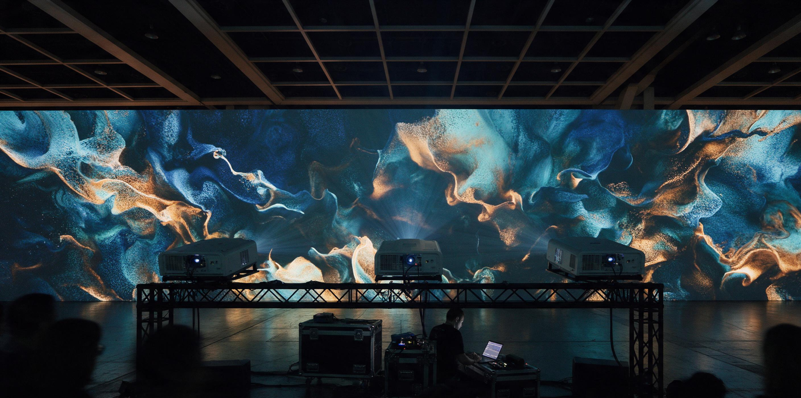
Edge blending projection joins two or more projectors into one continuous image by overlapping their edges by 10 to 15 percent and electronically tapering the brightness in that overlap so the joined area matches the rest of the canvas. Geometric warping then reshapes each projector’s output with a control-point grid so the combined image lands square on a real surface instead of a flat screen.
Three projectors, one image. It sounds like a purchasing decision, but it is really an alignment problem: three lenses, three slightly different panels, three angles of incidence, and one wall that was never designed to be a screen.
Edge blending and geometric warping are the two tools that make that array behave as a single canvas. Blending handles brightness where the beams overlap; warping handles geometry where the surface bends, tilts or steps back. Get both right and the audience sees artwork. Get either wrong and they see two grey bands running down the middle of a brand launch.
This article sets out the working numbers and the on-site sequence our team uses when a client needs a canvas wider than any single projector can throw, from a ballroom in Wan Chai to a harbourfront wall in Tsim Sha Tsui.
Key takeaways
- Blend overlap is normally 10 to 15 percent of image width; below 8 percent a seam becomes visible as soon as a projector drifts a few pixels.
- Blending only tapers brightness. Geometry, focus and colour still have to be matched unit by unit, or the overlap reads as a soft band.
- Warping uses a control-point grid per projector; a 3 by 3 grid suits a flat wall, a 9 by 9 or denser grid is needed where the surface steps or curves.
- Black level is the hardest part of blending: two overlapping beams make black grey, so the whole array is usually lifted to the brightest black in the system.
- Plan the canvas resolution from the native panels and the overlap, not from the final video file, or the artwork will be rescaled twice and lose sharpness.
What does edge blending actually do?
Edge blending makes the join between two projectors invisible by dimming the overlapping strip on both sides so the combined brightness equals the brightness of a single projector elsewhere on the canvas.
Each projector is set to fade from full output to zero across the overlap, using a blend curve rather than a straight line. A linear ramp looks obviously wrong to the eye because perceived brightness is not linear; an S-curve with a gamma correction of roughly 2.2 matches human vision closely enough that the strip disappears.
That is only half the job. Blending corrects luminance in the overlap. It does not correct a tilted image, a soft edge, a colour cast or a projector 40 pixels out of position. Those belong to warping, focus and colour calibration.
- Overlap width set in pixels and in metres, then checked on the actual surface
- Blend curve and gamma matched between the two units meeting at each seam
- Black level lifted across the whole array so the overlap matches black elsewhere
How much overlap should a blend zone have?
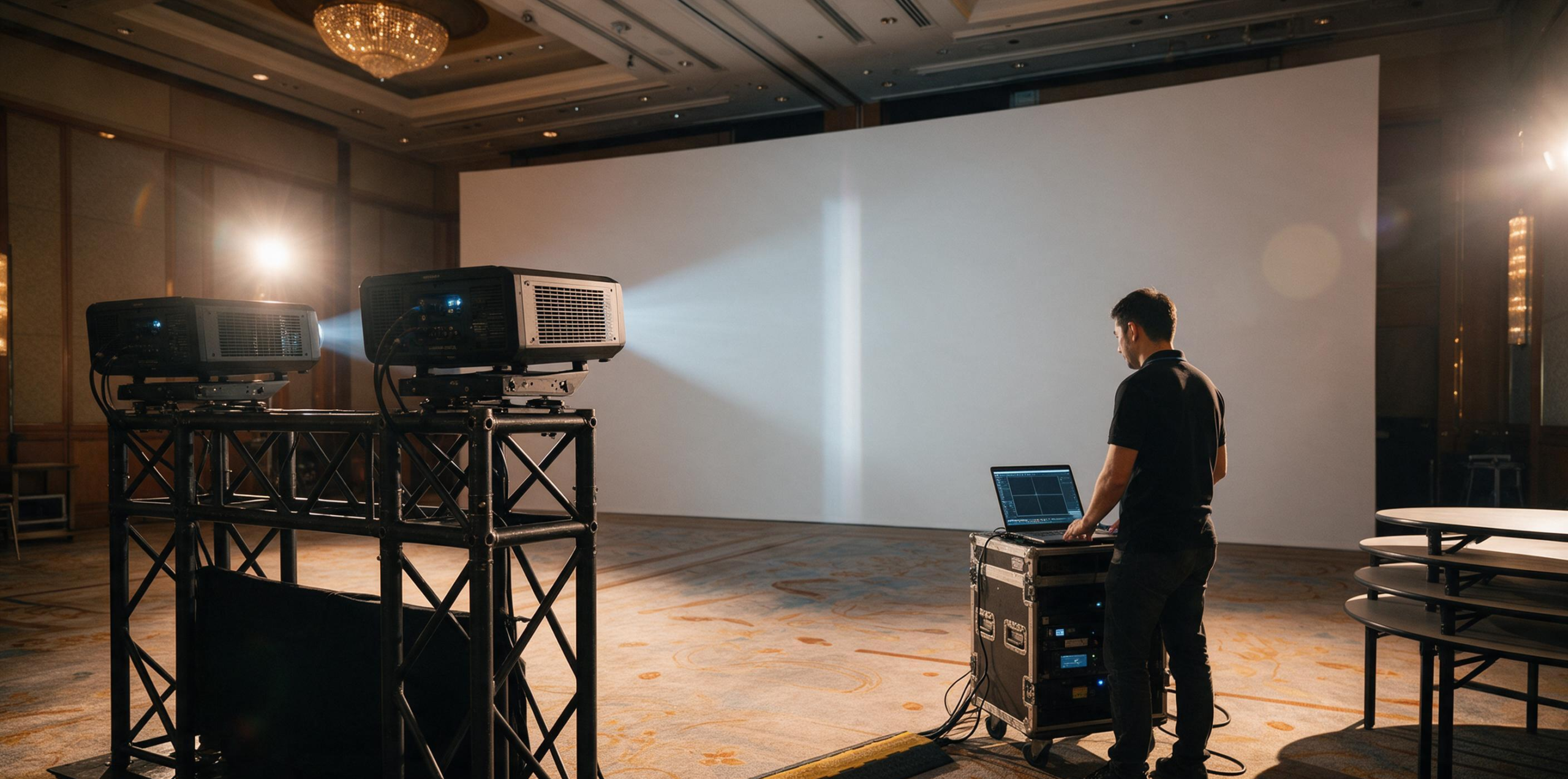
Ten to fifteen percent of image width is the working standard, and fifteen percent is the safer figure for a temporary event build where projectors may shift slightly during the run.
Overlap is not free. Every extra percent of overlap is resolution and light spent on the same piece of wall, and it also widens the strip that has to be matched in colour and black level. Below about eight percent, a two-pixel drift between units produces a visible line. Above twenty percent, the blend zone becomes wide enough that any mismatch in gamma shows as a soft grey band rather than a hard seam, which is often harder to fix.
The table below is the practical version we work from when specifying a horizontal array on a flat or near-flat surface.
| Overlap (% of image width) | Result on a temporary event build | Typical use |
|---|---|---|
| 0–5% | Visible seam, worst case a bright or dark line | Not used; only acceptable when a physical pillar hides the join |
| 8% | Acceptable if the truss is solid and nobody touches the lenses | Fixed installation with locked-off projectors |
| 10% | Standard for event work with stacked or flown units | Two-projector wide screen, stage backdrop |
| 15% | Most forgiving; hides small drift and grid rounding | Three-projector arrays, outdoor builds, multi-day runs |
| 20%+ | Blend band can read as a soft grey stripe if gamma is off | Curved or stepped surfaces where the join must be steered |
How does warping put the image on a real wall?
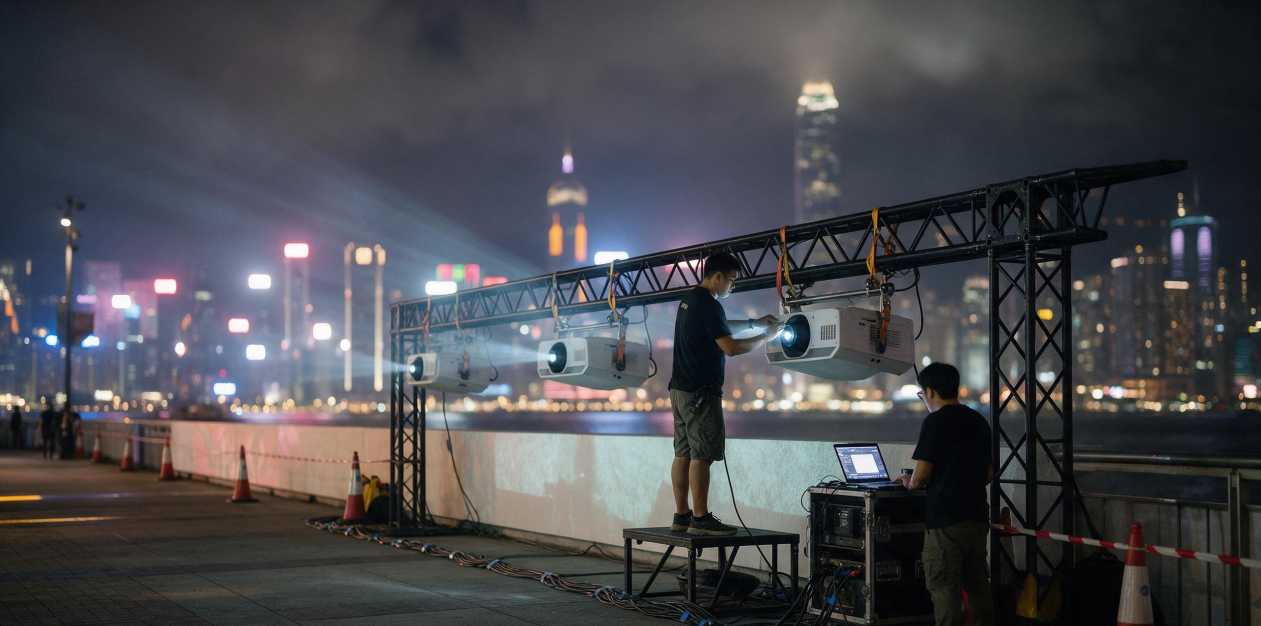
Warping reshapes each projector’s rectangle into a quadrilateral or a curved patch so the combined output lands on the surface as a single undistorted image.
The tool is a control-point grid covering the projector’s output. A 3 by 3 grid can handle a flat wall viewed off-axis, because all that is needed is a corner-to-corner correction. A wall with a column, a recessed window band or a change of plane needs a much denser grid, often 9 by 9 or 16 by 16, so the image can be pushed around the obstruction instead of across it.
The work is done in the media server or in the projector’s own warp engine, and the choice matters. Server-side warping keeps every projector identical and lets the whole canvas be manipulated as one file, which is what you want for content changes. Projector-side warping survives a server failure but has to be repeated on every unit, and the grids are harder to audit when something drifts.
- Coarse grid for flat surfaces, dense grid for steps, curves and obstructions
- Corner alignment first, then intermediate points, then fine trimming at the seams
- Warp stored per projector and exported as a backup file for the second show night
- Mesh warp rather than keystone wherever possible: keystone costs resolution and cannot bend
What is the on-site alignment sequence?
The sequence is fixed, and skipping a step is how a crew ends up at 3 a.m. re-doing work it already did. Physical first, then focus, then geometry, then colour, then blend, then content.
Start with the projector positions: height, angle, yaw and roll, all locked and safety-bonded before anything electronic is touched. Then zoom and focus at the actual throw distance, running the units for twenty to thirty minutes first, because focus shifts as lenses warm. Only then touch the warp grid. Geometry before colour, because moving an image changes which part of the panel is used.
Colour matching comes next: white balance and gain trimmed unit to unit against the same patch of wall, with the blend curves temporarily disabled so the overlap is at full brightness. Blending is applied last, one seam at a time, from the centre of the array outward. Content is loaded only when the array is already seamless on a grey test pattern.
Why does a seam still show when the overlap is correct?
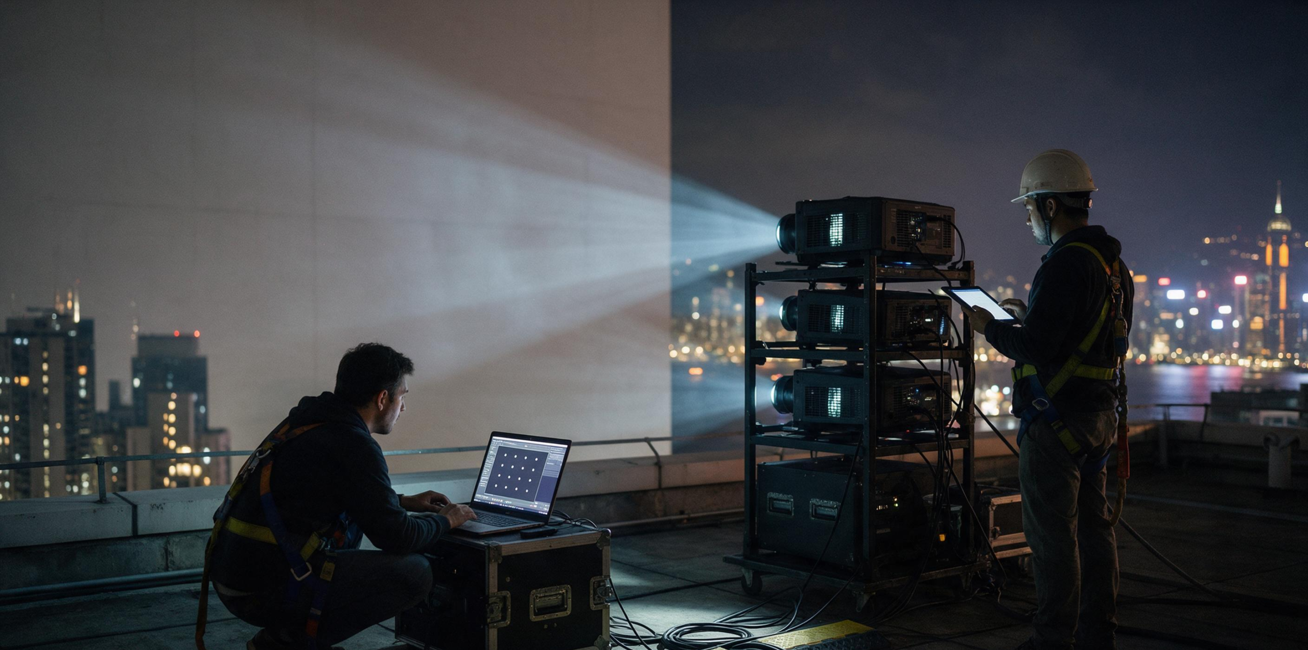
A visible seam with correct overlap is almost always a mismatch in something other than width. The five causes below cover most of what we find on site.
Black level is the most common and the least intuitive. Two beams overlapping produce twice the light in the overlap, including in black areas, so the strip glows slightly grey against the rest of the canvas. The fix is to raise black level across the entire array until the overlap matches, which costs some contrast but removes the band. On a dark scene, that trade is worth taking.
The others are mechanical and optical: a blend curve whose gamma does not match its neighbour, a projector with a different lens or far more laser hours so its white point has aged differently, a surface with a sheen that favours one angle of incidence, and a truss that flexes when someone walks on it.
- Black level not lifted: overlap glows grey in dark content
- Blend gamma mismatched between the two units at the seam
- Colour or brightness drift from unequal lamp or laser hours
- Surface sheen or texture that favours one angle of incidence
- Mechanical movement of the truss, stand or projector mount during the run
What hardware does a blended array need?
Three things have to be right before blending is even possible: enough lumens per unit, lenses matched to the throw, and a playback system that can drive the whole canvas as one output.
Lumens are arithmetic. Required output for the whole canvas is target lux multiplied by surface area, and that total is then split across units, with headroom for the 10 to 15 percent overlap and for ambient light at the venue. A 16-metre-wide canvas at 150 lux in a dark ballroom is a different specification from the same width on a lit waterfront.
Lenses must be identical across the array where possible. Mixing focal lengths forces different zoom settings, which changes distortion and makes warp grids harder to match. On playback, the array is one canvas at the combined resolution, each projector taking a fixed slice; the media server handles slices, blend and warp, and the show runs from one timecode.
- Identical projector model and lens across the array where budget allows
- Media server with enough outputs to feed every unit natively
- Network switch and cabling rated for the show length, with a spare output
- Export of the warp and blend files kept with the show file for night two
| Parameter | Worked example | Note |
|---|---|---|
| Units | 3 × 15,000-lumen laser projectors | Same model and lens across the array |
| Image width per unit | 6.0 m | Set by throw distance and lens, not by the video file |
| Overlap | 15% = 0.90 m per seam | Two seams in a three-unit array |
| Total canvas width | 18.0 m − 1.80 m = 16.2 m | Overlap is spent twice, once per join |
| Canvas resolution | 1920 × 3 − 288 × 2 = 5,184 px wide | Based on native panel width, not scaled video |
When is an LED wall the better answer?
Blended projection wins when the surface is the point: a wall with texture, a facade, a set piece, anything the artwork should appear to belong to. It also wins on budget for very large areas, because projectors cover square metres cheaply once you already have the rigging.
An LED wall wins when the event happens in daylight, when the client needs guaranteed contrast, or when there is no usable throw distance. Our LED wall stock is P2.84, which is a sensible pixel pitch for viewing distances from a few metres outward, and it does not care about ambient light or surface colour.
The trade is weight, power and cost per square metre. LED needs power distribution, a structure and a crew that can build it, whereas a blended projection array needs distance, darkness and alignment time. Between the two, the venue usually makes the decision for you. Our portfolio shows both routes on live events, and the service overview covers what each includes.
- Choose projection when the surface itself should be part of the design
- Choose projection when the canvas is larger than any practical LED build
- Choose LED for daylight, high ambient light, or no throw distance
- Check power and rigging load before committing to either
Frequently asked questions
How much does edge blending projection cost in Hong Kong?
Cost depends on projector count and class, rigging, media server, alignment time and content. As a reference, projector rental runs at roughly HK$2,000 to HK$3,000 per unit per day depending on model, and a blended array also needs a media server, an operator and additional alignment hours. Ask for a quote that itemises units, server, crew days and content separately.
How many projectors do I need for a seamless wide image?
Divide the required canvas width by the widest image one projector can throw at your available distance, then add 10 to 15 percent overlap per join. A 16-metre canvas on a 6-metre-per-unit throw needs three units with two overlaps, not two units stretched.
Can edge blending fix a wall that is not flat?
Blending itself only handles brightness in the overlap. Geometry on a non-flat wall is handled by geometric warping, using a denser control-point grid where the surface steps, curves or is obstructed. With enough grid points and enough projectors, most architectural surfaces can be mapped, but the content has to be built for the resulting mesh.
How long does it take to align a three-projector array?
Allow two to three hours on site for a three-unit array on a flat surface once the projectors are hung, focused and warmed up, plus a separate rehearsal slot for content. Stepped or curved surfaces, or a change of content after the first run, add time.
Why does the overlap look grey in dark scenes?
Because two overlapping beams deliver twice the light in that strip, including where the image should be black. The standard fix is to raise black level across the whole array so the overlap matches the rest of the canvas, accepting a small contrast loss in exchange for removing the band.
If your canvas is wider than one projector can throw, send us the venue, the surface dimensions and the date. We will come back with a unit count, overlap plan, rigging outline and alignment schedule. Talk to our projection team.